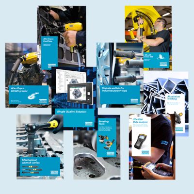
Need help selecting the right tools for your application? Check out one of our buying guides to get started!
Buying Guides
Dimensional drawings, Safety Information, Product Instructions, Manuals and User Guides
Servaid

Time to calibrate?

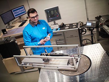
Secure your quality and reduce defects through Tool Calibration and Accredited Quality Assurance Calibration.​
power tool calibration, tool testing, metrology, machine capability test

View all our industries

Our industries
Unlock a world of valuable insights without the spam: Subscribe to our monthly newsletter and stay ahead with the latest industry innovations, expert tips, and cutting-edge solutions tailored for your success.
Subscribe Today
In this series of educational videos, our ‘Lab Boss’ Jason Benford performs various torque tests to show off the power and durability Atlas Copco tools have to offer!
In the Lab
Close

The design and working principle of the vane air motor

Vane air motors are produced with power ratings up to approximately 5 kW. It has a basic design and consists of only a few components.


Design

A slotted rotor rotates eccentrically in the chamber formed by the cylinder and cylinder end plates. Because the rotor is off-center and its diameter smaller than that of the cylinder, it creates a crescent-shaped chamber. The rotor slots contain air motor vanes that move freely, dividing the chamber into separate working sections of varying sizes. The combination of centrifugal force and the pressure of compressed air pushes the air motor vanes against the cylinder wall to seal each chamber. The effectiveness of this sealing process directly impacts air motor efficiency, as it depends on minimizing internal leakage.

Vane air motor components

1. Front end plate 2. Rotor 3. Vane 4. Cylinder 5. Rear end plate

Working principle

Air motor working principle

Working principle of an air motor

A. The air enters the inlet chamber “a.” Vane 2 has just sealed off chamber “b” between itself and vane 3. The pressure in chamber “b” is still the inlet pressure. This pressure acts on vane 3, moving it in a clockwise direction. B. The vanes have rotated further and the expansion process in chamber “b” has started. The pressure in the chamber is reduced, but there is still a net force moving the rotor forward as vane 3 has a larger area than vane 2 in chamber “b.” Additionally, the inlet pressure applies force to vane 2 within the inlet chamber "a." C. The vanes have moved further. Chamber “b” is now being emptied through the outlet and there is no more contribution from this chamber. The force moving the rotor forward now comes from the force on vane 1 and vane 2.

Thanks to this principle, the energy of the compressed air is converted into rotational motion as it moves from one chamber to another, causing the motor to turn.
Take a look at our product range
 
Find out about air motors' applications
 
Download library for more resources
 
Contact us!
Contact us!