Overview
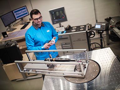
Atlas Copco's Industrial Location Guidance (ILG) is an integrated, stand-alone error proofing system that offers high-level process security for applications ranging from simple to complex.
ILG tracks the exact location of the tool relative to the fastening position, ensuring the correct fasteners are tightened to specification, in the proper sequence.
Comprised of ILG software, positioning hardware and tightening controller, the system combines the functionality of a tightening system with position and process control.
Typical applications for ILG include: low-volume, high-value component assembly, repairs stations and flexible assembly cells.
Benefits of ILG - Industrial Location Guidance
System features
• Tool enable dependent on its location relative to tightening position.
• Free or Forced process order.
• Initiate process from Workpiece (Part) ID on-screen input, barcode scanner, Stacklight, or fieldbus protocol.
• Workpiece process selection by controller identifier via barcode scanner or fieldbus communication protocol.
• Compensation for variable part location relative to the ILG system:
- Static part
- 1-Point Dynamic Referencing
- 2-Point Dynamic Referencing
- 3-Point Dynamic Referencing
• Configurable reject management – select number of tightening position retry attempts.
• Configurable graphical user interface for operator guidance with Workpiece image(s), live tracking (crosshairs) of the
tool’s location, visualization of the tightening position status and diagnostics.
• Teaching Mode allows the tightening positions to be set up with a start and finish position. The tool is held in position
and coordinates are stored with a touch of a button or tool trigger.
• Programmable Position Volumes (spheres, cylinders, or cones) depending on the application.
• Setup via web browser.
• Password protection available for configuration editing.
System components
An ILG system is comprised of:
• ILG software
• Positioning hardware
• Tightening controller
• Industrial PC (optional /dependent on application)
The positioning hardware includes high precision rotary or linear position sensors that are integrated into the pivot joints or linear guides of a torque arm or similar applications.
The sensors interface with the tightening controller or the Industrial PC via a gateway module. The gateway module communicates with the ILG service using Modbus TCP protocol. The ILG service communicates with the tightening controller through Open Protocol.
Multiple Atlas Copco tightening controller models are compatible with the system and various positioning hardware configurations are available to suit the different arm types.
Operation and function of the system
The ILG service receives the data from the positioning hardware sensors to calculate the tool location in three-dimensional space, in real time. Once the tool is located in the specified position, the ILG service will select the tightening program (P-Set) and enable the tool through Open Protocol. Visual indicators, via a Stacklight, tool LEDs, or the HMI process screen, will alert the operator to initiate the tool start.
ILG functionality:
• Monitors the location of the tool in the working area.
• Guides the operator through the correct work sequence.
• Automatically selects the tightening parameters for the position.
• Ensures the correct fasteners are tightened to specification.
• Unique P-Set selection for each position for full traceability.
Process order control
Depending on process requirements and the application, ILG can be
configured for certain process order control.
Free order
• The operator is free to choose the tightening sequence (or order)
of the positions.
• Visual indication is given when the tool is in a specified tightening
position.
Forced order
• The operator is not free to choose the tightening sequence (or
order) of the positions. The operator must follow the defined
sequence.
• Operator guidance is provided via a blue position indicator at the
specified tightening position.
• Visual indication is given when the tool is in a specified tightening
position.
• Position indicator displays in red or green, providing operator
confirmation of the tightening result.
Static & dynamic referencing
Depending on the application, ILG can be configured to compensate
for variable part location relative to the ILG system.
Static
• The part is introduced in the same location every cycle.
1-Point dynamic referencing
• The part is introduced in different linear locations (allows for linear
translation of part across any axes: x, y, and z).
2-Point dynamic referencing
• The part is introduced in different linear locations and rotated
(rotational location in a single axis only).
3-Point dynamic referencing
• The part is introduced in variable locations in all axis (allows for
linear or rotational translation of part across any axes: x, y, and z).
Downloads
- ILG - Industrial Location Guidance Brochure.pdf 6.5 MB, PDF


